One of our Newsletter followers requested a video on our Autopilot installation, which we had done last year. With the only other footage being a whole load of what can only be called wee jobs then this seemed like as good a time to get that video put together.
It was a great day on Salty Lass as all the equipment that we needed for our auto pilot install had finally arrived. We had even found a great space at the back of the rear cabin that was nice and dry and had plenty of room for all the equipment that we needed to install.
So one of the very first problems that we needed to overcome was where to fit the MK2 Wheel drive unit, so what we did was create a cardboard cut out of the wheel so that we could decide where exactly we could cut the hole required to install the unit. Of course the hole would not be on a straight bit of panel, but that seems normal, for an installation of this kind.
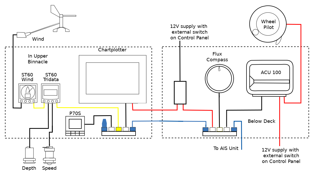
Our next issue came with where were we going to fit all of this equipment. We wanted the main area in the binnacle for the chart plotter, so that meant that we would need to re-house the old depth sensor and wind instrument, so to re-house these we bought a NASA Marine Clipper Twin Instrument Mounting Pod. We would also need to house our new P70S Control Head, so for this we bought a weatherproof IP65 electrical box which came in at about a tenth of the price of what they were asking for a marine equivalent. These boxes were not a perfect fit, for the instruments that we wanted, but with a little help from Leeloo our Multi-tool and a hole saw than they soon were.
Once we had got all our boxes altered, it was time to start putting everything together. So the first thing we did was put everything together in what can only be described as a lash up job. This allowed us to test everything and make sure that everything was working. Once everything was tested it was just a case of putting everything in neatly. In order to do that then I attached our inclinometer onto the template for the autopilot controller. As a way of getting the template straight, this worked really well, as I could see when the template was level, while with a spirit level, you need to be above the level to see and I was below.
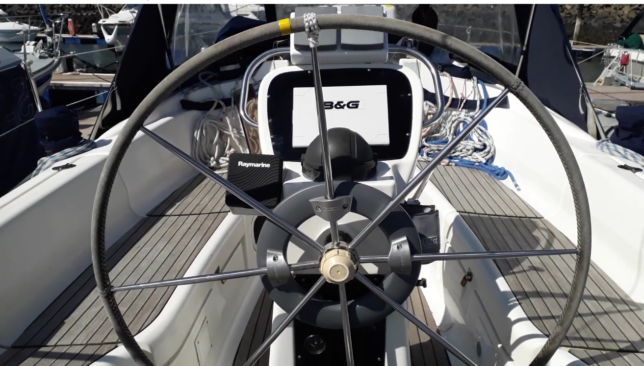
While I was working below deck, Beverley mounted all the new instrument pods and started fitting the new NMEA 2000 network. She also made a new panel made out of Acrylic to mount the new B&G Chart plotter. Once all the bits and bobs were put together on the top section of the binnacle it was tine to start on the bottom section of the binnacle, solving some of the problems that that installation presented us with.
So in the Raymarine box, we had a bracket that was designed to mount onto a pedestal with a curved mount and our binnacle was flat, so we could buy the correct bracket at £80 or we could put a sleeve oner a stainless steel bolt. Even the bolt that we had, needed to be altered by us adding a sleeve so that the bolt would be straight as it came our of the binnacle. Just putting in the bolt was a job and a half as I stretched holding the inside of the bolt and Beverley added nuts to the outside, but soon it was all sorted.
Once we had got the MK2 Wheel drive unit installed we hit upon another problem, in that the handle that locked the wheel, hit our slopped instrument panel including our fuel gauge and we felt that this was not satisfactory. So what we did was get another piece of black acrylic and made a new instrument panel that was flat. This caused another problem in that the cable that went to the engine now interfered with the steering gear, but with careful manipulation we could move this cable to somewhere else, where that no longer happened.
Back to the future
One of the things that we had done was replace our bumpy instrument panel with a flat panel, because the handle of the autopilot hit the bumpy panel, but what another channel had done was take an angle to the handle and modified that. Not something that I would like to do on day 1, but it is a solution.
So over the time that we have had it, then it has lost its compass bearing a few times, so when it does that then we have to put the engine on and drive around in circles, while we run the calibration routines, if we are sailing however we ignore what it says and just organise the sails so that it is balanced.
The autopilot has a maximum draw of 7Amps, but that will be when it is working a lot, in practice, you balance the sails, then the autopilot does not need to work as hard. Also when it is heavy weather then we will tend to hand steer as we can read the waves, while the autopilot will not.
In general, it has done what we wanted and allowed us to have breaks while we are steering, also it can get wet while we shelter below decks, so in general we will give our Auto pilot a thumbs up.
